This topic should be reviewed by anyone who wants to use an external SVG editor, such as Adobe Illustrator, to decorate an exported SVG with artwork, then have that artwork incorporated in future exports -- merged exports -- from Walls. The details presented here aren't needed to simply export SVGs as you would metafiles, to view and print SVGs with Walls2D, or to perform merged exports using source SVGs decorated by someone else.
The SVG export function places graphical content into specially named layers. The names are preserved when the SVG file is read and rewritten by Illustrator. (Note that a layer name, like w2d Walls, will appear with an underline ("_") instead of a space character in the SVG text file. You should avoid the underline character when manually entering layer or group names while in Illustrator.) During a merged export operation, when Walls reads back an SVG decorated with artwork, the layer names determine how the new content is to be treated when it's combined with revised survey data. Content outside of these layers is not automatically included in the new SVG that's written. This layer-specific treatment is described below and also in Adjustment of Brushed Strokes.
Required Layers for Roundtripping
As will be explained in more detail below, the particular w2d layer where artwork is found will determine how Walls adjusts it. For example, when you export a new merged SVG, it might have both a new scale and a different north arrow direction. The reason you would place passage-defining rocks and large boulders within a shp sublayer instead of a sym sublayer is to insure that their north-relative orientations are preserved as much as possible. The adjustment will scale, translate, and rotate the objects as required. Also, unless the objects are enclosed in an unnamed group within the shp layer, their paths will also be reshaped, with each control point being shifted separately. By contrast, all sym objects, including paths, are adjusted while preserving their page-relative orientation. Sym objects are never reshaped, just translated and scaled. Also, sym objects inside an unnamed group maintain their relative positions -- exactly what you would want for objects making up a cross section or ceiling height symbol.
Important Note: Layers and groups are different kinds of objects in Illustrator, with groups shown in light gray rather than dark gray in the layers palette (see image below). The SVG format, however, makes no distinction between layers and groups. As a result, the special SVG layers that Walls creates and operates on are initially interpreted by Illustrator as groups. Since targeting a group with new artwork can be less convenient than targeting a layer, you'll probably want to convert the groups you intend to work with into Illustrator layers. This can be done quickly by running a script immediately after opening the file. (For details, see Converting Groups to Layers in Illustrator.) In this topic, all of the w2d groups and layers will be referred to as "layers."
|
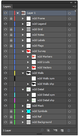
When an SVG freshly exported from Walls is first opened in Illustrator, the Layers palette will show a sequence of layers and groups reflecting the selections you made in the SVG Export dialog. The image at left shows the palette after the script was run that converts eight of the w2d groups to layers.
Although the layers are individually described below under Layer Descriptions, some general properties are worth noting first. While most layers are optional, their listing order in the Layers palette is important and should be maintained as you add artwork. Objects appearing higher in the list will be rendered after the objects beneath them are rendered, possibly obscuring them. (The listing order is reversed in the SVG file itself, where listing order matches rendering order.)
Layers for Interactive Access - The w2d Walls, w2d Detail, w2d Survey, w2d Labels, w2d Flags, w2d Notes, and w2d Grid layers are recognized by the integrated SVG viewer, Walls2D, where their display can be toggled on and off. This may affect your choice of what to place in each layer, either when exporting from Walls or when adding artwork.
Merged Layers - When an adjustable SVG file without merged content is exported from Walls, the w2d Legend, w2d Walls, w2d Detail, and w2d Mask layers are present but empty. It is within those four layers that you are expected to add artwork. (Note that these are "unlocked" layers in the example at left.) The w2d Walls and w2d Detail layers each consist of two sublayers: one with a name ending in "sym" and another with a name ending in "shp". The sym layers will contain elements, such as text and symbols, that must maintain their shape and page-relative orientation during an adjustment by Walls. By contrast, the shp layers and the w2d Mask layer will contain paths, like cave wall outlines, whose control points must be adjusted individually. The shp layers can also contain non-morphable objects which must maintain their shape and north-relative orientation. Finally, the w2d Legend layer will be subject only to translation and scaling as a group. In any merged layer but the legend layer, the locations of objects will individually track the positions of nearby survey vectors.
In each of the merged layers you are free to define new sublayers or groups with names of your choosing. (If a group is named, the name must be unique within the document.) Their entire contents, including style attributes, will be preserved during roundtripping with Walls. The shapes and positions of contained objects, however, will be subject to adjustment if the survey data, map view, or scale changes. The specific features of the merged layers will be described below.
|
Inheriting Styles from Non-merged Layers
The remaining layers (survey vectors, labels, flags, etc.) are always regenerated from project data during an export operation; you'll normally leave them untouched when adding artwork. Note, however, that there is an SVG Export dialog option named Preserve styles and colors. If you leave that option enabled, the program will retrieve certain style attributes from layers in the merged SVG as opposed to taking them from current project settings. Those attributes could have originated from an earlier Walls export, from edits in Illustrator, of from manually editing the SVG as text. Here are the specific attributes inherited from the non-merged layers when the option is enabled:
w2d Frame |
- Ratio of outline stroke width to total frame width. |
w2d Grid |
- Color and stroke widths of major and minor grid lines. |
w2d Notes |
- Typeface, size, and color as obtained from first-encountered note (first in SVG). |
w2d Labels |
- Typeface, size, and color as obtained from first-encountered label. |
w2d Flags |
- All attributes of symbols assigned to named station flags including instance sizes. |
w2d Markers |
- Station marker symbol and size as obtained from first-encountered instance. |
w2d Vectors |
- Colors of all vectors and stroke width as obtained from first-encountered vector. |
w2d Ref |
- Font point size of map title and georeference information. |
w2d Background |
- Background color (or passage color if there is a merged w2d Mask layer). |
Required Layers in the Merged SVG
Layers in the above list that are present in a merged SVG are examined only for their style attributes and for information needed when adjusting artwork. Only w2d Ref and w2d Vectors are required to be present. (They are needed to correlate the merge file's contents with the project database.) In both merged and non-merged exports, the elements in these nine layers are rebuilt each time based on export options and the current state of the compiled project. The option to inherit styles, however, frees us from having to worry about display settings during merged exports that create adjusted, possibly zoomed views of an existing SVG source file. This will be a very common operation.
Size Scaling
When a new view of an existing SVG map is generated, any size attributes inherited from the merged SVG are actually scaled so that the apparent sizes (or thicknesses) of objects in world coordinate units remain the same. For example, a station marker that appears 30 cm wide in the merged SVG will also appear that large in the new SVG even though the map scales may be different. Likewise, the stroke thicknesses of passage outlines and other drawn objects in the merged layers will remain in constant proportion to the map's scale bar. The effect is the same as zooming interactively within the Walls2D viewer. Whenever this is not the effect you want for the non-merged layers, you should uncheck Preserve styles and colors and set up the display attributes (font sizes, background color, etc.) in Walls prior to exporting. As for an initial non-merged export, this requires that you consider carefully the Scale & Position dialog settings for the project item being reviewed and also the scales at which the SVG is likely to be viewed or printed. Remember that SVG images are rescalable and can be made interactive. Even if the SVG is too large to print in full detail, high-resolution, printable images can be made from smaller portions of it.
Controlling Overlap of Labels and Notes
Finally, there is another Advanced SVG Export option, "Preserve Visibility and Positions of Labels", that causes station-relative offsets of both notes and labels to be inherited from the merged SVG. There is no automatic overlap control in SVG map labeling, but this feature allows you to manually adjust, while in Illustrator or another editor, the positions of individual elements in these layers to avoid severe cases of clutter. Specific station labels (but not notes) can be deleted as well. This means that if a vector endpoint exists in the merged SVG, but is missing a label, it will also not have one in the new SVG.
The SVG document elements recognized by Walls are described below in the order they would appear in Illustrator's Layer window. This order is opposite the rendering order, or order of appearance within the SVG file itself. The names in bold type are the XML group id's that any SVG editor must preserve. Unless they are on grayed top-level layers, Illustrator sees these as group names rather than true sublayer names. When Illustrator reads back an SVG, the distinction between sublayers and groups is lost for all but the top-most layer or layers. This is easily fixed for Walls-exported SVGs, however. (See Converting Groups to Layers.)
w2d Frame - Consists only of a non-filled rectangle with black outline surrounding the view frame. The frame dimensions are always determined by Walls settings for the compiled branch at the time of export (Scale & Positiondialog). The outline stroke width, when not inherited from a source SVG, is taken from the frame's "Line width" setting in the Printer: Map format Options dialog. (A zero thickness omits the frame.) When it is inherited, it's actually the ratio of stroke width to frame width that's preserved. This causes the outline to look much the same as it did in the merged file when the new SVG is viewed full-screen.
w2d Legend - A layer that's always present in an adjustable SVG export, but empty unless a merged SVG has content in this layer. In the latter case, the layer will be duplicated in the merged export, including all symbols and their instances. You may want to use Illustrator to create at least a map title, scale, and north arrow in the legend layer. At least one text element is required if the layer is used at all. In a merged export, the entire layer will be translated and scaled so that the first-rendered text element has the same world (not page) coordinates. Unless a new plan view is being established (survey rotated), the world coordinates will in fact be unchanged for all elements. An exported zoomed view might contain no legend or just a partial legend, even though you've chosen to include it. If the map's datum or zero reference in the merged file differs from that in the compiled data, the legend might be shifted entirely out of view. (In an adjustable SVG export the entire contents of the w2d Legend layer is included, even if outside the frame.) Also, if you change the plan orientation, any north arrow in the legend layer will need to be manually revised in Illustrator. Note that the w2d Ref layer (described below) will always contain the map title and georeferencing information.
As with earlier Walls releases, the w2d Legend layer can optionally be positioned immediately above the w2d Walls layer. Placing it above w2d Grid, as described here, can result in more attractive maps -- especially if you use legend boxes (possibly with drop shadows). For an example of this, see the Tutorial Project sample.
w2d Grid - Consists of horizontal and vertical lines of an optional 2-level square grid. The major grid interval in meters and the number of subintervals are always specified in the SVG export dialog; they are never inherited from a source SVG. The grid's style, however, can be inherited. When not inherited, the stroke width of minor grid lines is the same as that used for survey vectors (0.03 times label type size) and the width of major grid lines is five times as large. The grid color, when not inherited, is the one specified on the Segments page of the Review dialog. The grid lines are always assigned an opacity value of 0.5, which makes them fainter and allows objects beneath them to show through.
w2d Notes - An optional layer consisting of notes (text strings) that have been assigned to stations in Walls. If notes are exported at all, a note is omitted only when the associated station is unflagged (or with only hidden flags) and the option "Hide notes for unflagged stations" in the Flag and Marker Symbols dialog is checked. When not inherited, note color is specified as usual on the Segments page's control panel and font size is specified in the Printer: Map format Options dialog. The typeface, however, is initially a Times New Roman italic font, but like the other attributes it can be inherited. A note, by default, is positioned above-right of the station marker to avoid obscuring the station's label, which is normally below-right. Positions of individual notes can be inherited as described above (Controlling Overlap of Labels and Notes).
w2d Labels - An optional layer consisting of text elements representing station names. Up to eight characters of the name prefix, with colon separator, is included whenever the option to show prefixes is enabled in the Printer: Map format Options dialog. This dialog is also be used to control the initial font size and station-relative offsets. Text color is specified on the Segments page's control panel. The initial typeface is Arial but this, like all font properties, can be inherited from a merged SVG. Text overlap can be controlled manually as described above under Controlling Overlap of Labels and Notes. Unlike notes, labels deleted from a merged SVG will not be reintroduced in the new SVG when the preserve visibility option is selected. For initial SVG exports, label font size should be chosen carefully since it is also used to calculate an initial marker size and stroke width for vectors. For map scales of around 1:360 (1"= 30 ft), I would suggest a font size of about five points.
w2d Flags - An optional layer of symbols centered at stations that have been assigned the corresponding flag names in Walls. A flag symbol's initial style and appearance (visible or hidden) is controlled as usual from within the Flag and Marker Symbols dialog. In a merged export, both the symbol definitions and the sizes of their instances can be inherited, although instances for a particular named symbol will have the same size (the size of the first encountered instance in the source SVG). When an exported SVG is brought into Illustrator, the Symbol window will show the symbols used in this layer along with the station marker symbol and symbols used in other layers. Their names will be the actual flag names prefixed with an underline. Assigning the "transparent" style to a flag symbol in Walls produces an SVG symbol with "fill-opacity" 0.5. The effect is that station markers would be visible beneath assigned flags.
w2d Survey - The parent layer of w2d Markers and w2d Vectors. Those sublayers are grouped to allow toggling of Survey visibility in Walls2D via a single control. They comprise the entire content of this layer.
w2d Markers - A sublayer of w2d Survey containing instances of a station marker symbol named "_m". Both the symbol definition and the sizes of its instances are inheritable from the first-encountered marker instance in a merged SVG. Otherwise the symbol is defined as a solid square with a color that's specified in the Flag and Marker Symbols dialog. When not inherited, the width of a marker instance is 0.133 times the point size of a station label. A marker layer is created each time vectors are exported, but a merged SVG doesn't have to have one.
w2d Lruds - A sublayer of w2d Survey that's present when you've checked the box labeled "Include LRUD bars when vectors are exported" in the SVG Advanced Settings dialog. The color of the bars is not an inhertitable setting, but is always determined by what you have set for Passage Outlines on the Segments page. In Walls2D the bars and vector lines are toggled on and off as a group. Another advanced setting is support for cross-section outline boxes. If the "C" suffix was used when specifying an LRUD in the survey data, a rectangular box will accompany the bar. The box is drawn one meter to the right of the bar's right endpoint as one looks toward the LRUD's facing direction. The Illustrator user will need to reposition and page-orient the box if required, draw the section, then reflect the whole thing about the vertical axis if the box was originally upside down. See LRUD Passage Dimensions.
w2d Vectors - A sublayer of w2d Survey containing the line segments that represent survey vectors. Only in non-adjustable exports is this layer not required. When not inherited, the line colors are specified as usual on the Segments page of the Review dialog. Different segments of the survey can have different colors, including any of the three gradient types. The stroke width, however, is initially 0.03 times the point size of a station label (or 0.01 pts, whichever is largest). The stroke width can also be inherited from the first-encountered vector in a merged SVG. In an adjustable SVG export, each vector element has a specially constructed name, the XML id attribute, that uniquely identifies the two endpoint stations. This allows linkage to the Walls project database and makes adjustment of nearby map features possible.
There is a simple way to remove a vector's influence on the adjustment of features. For example, you may want to remove the effect of an overlying surface survey vector while not deleting it. You can do this in Illustrator by prefixing the path's existing name (the XML id) with a single space character. (The name will already have one starting space character if the vector's FROM station name begins with a digit.) In an SVG source file produced by Walls you'll need to do this by editing the SVG text -- except here you'll use the underline character ("_") which corresponds to the space you would see in Illustrator. When you use this technique, be careful not to alter the remaining portion of the name.
w2d Walls - An optional parent layer that's present in an adjustable SVG export, but empty unless a merged SVG has content in this layer (possibly drawn with Illustrator). It's intended for prominent map features, like passage wall outlines, which remain visible when the Detail layer is turned off in the Walls2D viewer. All objects in this layer must belong to either of two sublayers:
w2d Walls sym - An optional sublayer of w2d Walls containing symbol instances, text elements, and any path or group that can't be reshaped. It is here that you draw prominent map features like area names, geological symbols, passage cross sections, or anything whose survey-relative position must be maintained through translation and scaling alone. This is done by calculating a shift value for the center of the object's bounding box. (In determining a bounding box, Walls currently doesn't calculate the true extent of a text element; only the location of the bottom-left corner of the first character is considered.) Unlike passage wall outlines in the plan, which are subject to morphing, objects in this layer will maintain their shape and page-relative orientation during feature adjustment. Examples are the filled circles representing wells in Actun Kaua. After Illustrator 10 exports them to SVG, those objects are no longer easily identifiable as circles. Instead they are closed "paths" that are no different in SVG syntax from ordinary drawn columns or breakdown pieces. (This limitation of version 10 was removed in version CS, which exports a variety of basic SVG shapes, including ellipses.)
In both of the sym layers (w2d Walls sym and w2d Detail sym) an unnamed group is translated and scaled as if it were a single object. Furthermore, unlike a shp layer object, it maintains its page-relative orientation. Grouping a ceiling height number with its enclosing circle, for example, will prevent the number from becoming uncentered during an adjustment. Similarly, if you add details to a cross section, you'll want to group them with the cross section's outline. In Illustrator, an unnamed group is labeled "<group>" in the Layers palette.
w2d Walls shp - An optional sublayer of w2d Walls. It is here that you draw prominent reshapable features like passage walls, large breakdown, and major water boundaries. They include anything you would like to still see when the Detail layer is toggled off in Walls2D. Such features are represented in both Illustrator SVG text as <path> objects -- sequences of control points defining polylines or Bezier curves. During a merged SVG export, Walls updates each control point's position to fit the current best estimate for the cave survey. The latter could have changed since the features were drawn. By default, a shift value is computed for each control point that is a weighted average of the shifts in the six nearest survey vectors (their plan projections). This vector count, along with other weighting parameters, are options in the Advanced SVG Export Settings dialog.
Similarly to the sym layers, the shp layers (w2d Walls shp and w2d Detail shp) can also have non-morphable objects such as symbols, text, and paths in unnamed groups. Unlike such objects in the sym layers, however, these shp layer objects maintain their orientation with respect to the survey coordinate system, not the page. For example, in the shp layers you'll place path-aligned text and symbols representing large rocks and breakdown. (For efficiency sake, you should define and use symbols whenever possible. Note that different symbol instances can be transformed in different ways.)
w2d Detail - An optional parent layer that's present in an adjustable SVG export, but empty unless a merged SVG has content in this layer (possibly drawn with Illustrator). It's intended for less prominent, small-scale map features -- anything you may want to hide from view when the map is presented at smaller scales or magnification. All objects in this layer must belong to either of two sublayers:
w2d Detail sym - An optional sublayer of w2d Detail intended non-reshapable features whose visibility you may need to control independently of the w2d Walls sym layer. Candidate objects are ceiling heights, depth indicators, and representations of floor material like clay. The layer could contain symbol instances for geological, biological, or historical content if the w2d Flag layer isn't being used for this purpose. Since the w2d Flag layer will be rewritten (or entirely omitted) in a Walls export, you might want to move certain flag symbols to w2d Detail sym, possibly replacing them with fancier icons from Illustrator's symbol pallette. You'll also want to place cross sections in this sublayer since only their positions, not shapes, should depend on the locations of nearby survey vectors.
w2d Detail shp - An optional sublayer of w2d Detail, which is available for drawing both reshapable and non-page oriented features whose visibility you may need to control independently of the w2d Walls shp layer. Candidate objects are slope lines, dome and drop indicators, stream courses, pools, and breakdown. Like in w2d Walls shp, such objects can be either drawn or placed as symbol instances. In either case their orientation with respect to the survey is preserved.
w2d Mask - An optional layer which is treated during merge operations exactly like w2d Walls shp and w2d Details shp. Its visibility, however, can't be toggled off in the Walls2D viewer. As with the other layers intended to contain artwork, an empty w2d Mask layer is produced by a non-merged SVG export from Walls.
One reason for having such a layer is that it's often desirable to have different background colors for the cave interior (passage floor) and the non-cave regions. The way to accomplish this is to store in w2d Mask a duplicate of those paths in the w2d Walls shp layer that define passage outlines. The copy should then be modified as follows:
| • | Connect all paths forming the outer wall of the cave, creating a single closed outline path. Position this path as the lowermost path in the w2d Mask layer (or of a named group in that layer). Give the path a fill color that represents the floor of the cave. This color will be referred to as the "passage" color. |
| • | Close off all open paths located inside the cave outline, forming closed paths surrounding non-cave regions such as columns. Give all the interior closed paths a fill color that's different from the passage color. Normally this will be the map's background color. (See w2d Background.) |
| • | Finally, assign no stroke to all paths in the w2d Mask layer. |
|
The mask layer should be organized into one or more named or unnamed groups of closed paths. The lowermost (first-drawn) path in a group will be recognized as an outer path, which is normally filled with the passage floor color. The remaining paths in each group, the inner paths, can be filled with a different color, usually the map's background color when the inner paths represent columns or non-passage regions. Such grouping makes it easier to represent multiple disconnected caves in the SVG and also facilitates exporting to shapefile format as described below.
|
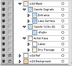
The mask layer has another important purpose. When compiling project data, Walls will optionally process (adjusting if necessary) an attached source SVG containing a mask layer. The program can then draw SVG-based, rather than LRUD-based, passage outlines on its displayed and printed maps without utilizing the Walls2D viewer. (See Passage Display Options.) The image detail and quality isn't as good as that of the complete SVG rendered by Walls2D (which uses Adobe's plug-in), but the operation is much faster. When drawing the passages, Walls observes the settings on the Segments page that specify passage floor color and background color. Those colors are then used to replace the corresponding colors in a processed SVG. (The fill color of the lowermost path in w2d Mask is considered the SVG's passage floor color. In the example above, this is the fill color of the bottom path in "Dry Passage".) The passage outline pen style and color can also be specified on the Segments page.
Finally, one of the five shapefile types that can be chosen during a shapefile export operation are the passage outlines. A shapefile of this type will consist of polygons constructed from the closed paths in the w2d Mask layer. Each group of outer and inner paths will be stored as a record in the shapefile, and the name of the group (concatenated with parent group names, if present) will be stored as a field in the shapefile's table component. Additional table fields are SVG file name and total floor area in square meters.
One feature of the shapefile export worth noting is that the colors assigned to inner paths in the SVG are ignored. Each shapefile record, which consists of one outer polygon grouped with zero or more inner polygons, is assigned one fill color attribute (which can be "no color"). If it's used as the basis of color assignments in ArcView, the outer polygons will be filled with those colors while the inner polygons will produce "holes" in the outer polygons. The above example gets around this restriction by placing Cenote Sagrado's "Entrance" and "Lake Surface" outlines in their own groups. This way, both will be treated as outer polygons. If the single path in "Entrance" had been grouped with the one in "Lake Surface" (but positioned just above it), it would be treated as an inner polygon. While Walls would show it as light blue (above the darker blue of the lake), ArcView would show it as a hole with no color. For the same reason, the individual paths in "Lakes" are placed in their own unnamed groups. This feature of ArcView is usually an advantage instead of a limitation. The "holes" in a cave floor allow other layers, such as background images, to show through.
w2d Symbols - This layer is produced by Walls in an adjustable SVG export where the source SVG contains added symbol definitions. It contains one instance of each symbol -- all positioned near the upper left corner of the page. The layer's only purpose is to work around an Illustrator CS bug. (When importing SVG, it obtains some symbol attributes, such as geometric transformations, from the first-encountered instance instead of the actual symbol definition.) After opening the SVG in Illustrator, you can delete this layer if you wish. You may want to keep it if you plan to roundtrip Illustrator's own SVG files as opposed to passing them through Walls -- something you should try to avoid for other reasons as well. See Instructions for Illustrator Users.
w2d Ref - A required "metadata" layer consisting of a single text element positioned at the lower left corner of the frame. It's part of every SVG exported from Walls and a file must have it to be accepted in a merge operation. The text consists of a map title and information used by Walls and Wall2D for georeferencing -- specifically the plan view (degrees), scale ratio, region width and height (meters), and center coordinates (meters). The format of this line of text must not be altered outside of Walls. The type size, however, can be inherited in a merge operation. Otherwise it's a setting in the Printer: Map format Options dialog (Fonts - Frame section). For an interactive map, I suggest a size that makes the text barely readable at maximum zoom level. A black Arial typeface is always assigned by the export function. You may want to hide the text completely if you have a legend. This can be done manually by finding line "<g id='w2d Ref'>" in the SVG text file and changing it to "<g id='w2d Ref' display='none'>". The effect is the same as toggling the visibility of this layer off in Illustrator before saving the document.
w2d Background - A required layer consisting of a single filled rectangle (no outline) which defines the map extent. The fill color, when not inherited from a merged SVG, is taken from the current background color setting for a displayed map in Walls. (See, for example, the Segments page's control panel.) If the color happens to be white (either specified or inherited) and the passage color of the w2d Mask layer is also white, then another style attribute, opacity, is assigned a value of zero by the export function. That's simply to make the map look less "washed out" when it's viewed in Walls2D or Adobe's SVG viewer -- a fix that apparently doesn't degrade performance. (Setting the fill attribute to "none" was not an option since a filled background is required for mouse movement to be detected.)