A shapefile export allows Walls processed data to be used directly by ArcView® and other GIS programs that support the ESRI shapefile format. With such programs you can associate your survey data with scanned topographic maps and aerial photos. In addition, many kinds of operations (sophisticated queries, feature highlighting, etc.) that Walls itself currently doesn't support can be accomplished.
Update: See Units and Geographical Reference Issues below for a recent enhancement of this export function. Also note that Lat/Long shapefiles are now generated by default.
To perform a GIS export, compile your project and select the Segments page of the Review dialog. Next, select the desired branch of the segment tree and click the "Reports" button (or right click on the branch). This brings up the Adjusted Totals dialog, which features several export options. Finally, click the button labeled Shapefiles. This brings up the following dialog:
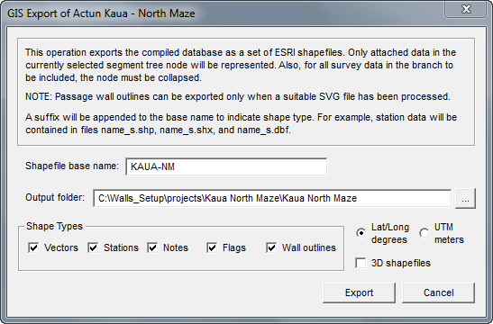
The Shapefile base name field specifies the output file name prefix. In this example, the shapefile containing vector data would be named KAUA-NM_V.SHP.
The Output Folder field specifies where all created shapefile components will be located. The initial default location is the project's workfile folder, but you can change it to the location of an existing GIS project.
Shape Types: Not only can vectors and coordinate information be exported, but also the text for station notes and flags and, if available, the passage outlines stored in a processed SVG file. The codes corresponding to the display attributes you've assigned to segment tree nodes will also be stored as shapefile attributes. This allows you to configure a GIS viewer's map so that its colors and line styles resemble those displayed in Walls. The attached/detached state of branches will be recognized during the export operation, allowing you to exclude data with certain segment attributes. You might want to perform multiple export operations, giving recognizable shapefile base names to different parts of the project (individual caves, surface surveys, GPS locations, etc.). Although it's possible to differentiate (e.g., with color assignments) data with different attributes in a single shapefile database, it might be more convenient to work with multiple shapefiles that can be selectively enabled as layers in an GIS project.
Lat/Long degrees or UTM meters: Although the compiled dataset consists of UTM coordinate values, you can specify that the geometry component of the shapefile should have Lat/Long degree values. This is the default choice, as most GIS viewers will accept such shapefiles regardless of whether or not a projection component (PRJ file) is available. Since PRJ files are generated for datums WGS84, NAD83, and NAD27 CONUS, UTM shapefiles with those datums should work equally well if the GIS program reads the PRJ file and, if necessary, converts the data correctly.
Update: Create 3D shapefiles: Check this box to create 3D versions of all chosen shape types except that of the Wall outlines (which are always 2D). For UTM shapefiles this causes a feature's elevation in meters to be stored as a Z value in the geometry portion of the shapefile. For Lat/Long shapefiles this elevation is scaled to degree units, which is a requirement of the format. The attribute portion (DBF file) will be similar to that of the 2D version. The 3D Analyst extension of ArcView allows viewing of 3D shapefile data at different profile orientations. The ArcView program itself will ignore the Z values. For best compatibility with other GIS software I recommend you choose UTM instead of Lat/Long as the coordinate type for 3D shapefiles.
Notes Regarding the Shapefile Types
The Flags shapefile will contain only the non-hidden flags as indicated in the Flags and Marker Symbols dialog. There is also a check box in this dialog labeled Hide notes for unflagged stations. When that box is checked, the Notes shapefile will contain just the notes for stations with non-hidden flags. The Flags and Marker Symbols dialog might also show flags that have been excluded from this export operation via the detachment of segment tree branches. Both those flags and the hidden flags are excluded from the Flags shapefile.
The option to produce a Walls outlines shape type is enabled only when the most recent compilation produced a workfile with extension NTW. Two conditions are necessary for this to happen when a project book item is compiled: 1) an SVG source file with a mask layer is attached to the project tree as a child of the compiled item, and 2) the Compile Options property, Process source SVG if one is attached, is enabled for that item. For more information on what's actually written to this shapefile, see the attributes section below and also the SVG Mask layer description in the SVG Layer Definitions topic.
An ESRI shapefile is actually a set of at least three files, each with the same base name but with different extensions: SHP, SHX, and DBF. To access them from ESRI's ArcExplorer, for example, perform these steps:
| • | In Walls, create a named shapefile database as described above. In this example, Kaua_V.shp, Kaua_N_shp, Kaua_F.shp, and Kaua_W.shp will be created (with associated SHX and DBF files) in folder E:\kaua\project\kaua . |
| • | Start ArcExplorer with an empty "Untitled" project and select the Theme | Add Theme menu option (or toolbar button). From the dialog that opens, navigate to the output folder you've selected for the export. |
| • | To add a listed shape file (extension .SHP) as a theme in your project, simply double-click the listed filename. Alternatively, you can drag-and-drop the SHP files to the program's map page. |
| • | Enable (display) the desired themes by checking their corresponding boxes on the map's legend. Finally, double-click each of the legend items to experiment with their visibility properties. |
Units and Geographical Reference Issues
The display and selection options available with GIS software such as that offered by ESRI are too numerous to be described here. Much of this depends on the attributes stored as fields in the DBF database that accompanies each SHP file. The shapefile format specification says nothing about what fields (named columns) should be present in the database. It does, however, state that each DBF file record (row) will be associated with a set of XY coordinates, a "shape" of a certain type, stored in the SHP file.
If your goal is to add your survey data as layers in a GIS project, you must first ensure that the exported files will have units compatible with the topographic images you'll be associating them with. Most likely, you'll want to overlay your cave surveys on maps keyed to a specific geodetic datum (such as NAD27 or WGS84). To accomplish this, you should run through the following checklist before exporting the data from Walls:
| • | Establish a geographical reference position for your Walls project (or relevant portion thereof). This is accomplished via the Geographical Reference page of the Properties dialog. |
| • | On this same page, make sure that the type specified for generated coordinates is UTM grid-relative. |
| • | In the SRV data files, ensure that all #FIXed stations (there must be at least one) have assigned UTM coordinates based on the same UTM zone and geodetic datum that's specified for the geographical reference. |
| • | Optionally produce a vector listing to confirm both the nature and quantity of the data you've selected to export. |
Starting with Walls Release B8, a fourth shapefile component, an ESRI-compatible projection file with extension PRJ, is produced in export operations where the assigned datum is either WGS84, NAD83, or NAD27 CONUS. (Other datums may have this support in future releases.) Also, the projection file will specify the type of shapefile coordinates you've chosen: UTM meters or Lat/Long degrees. The presence of a PRJ component greatly simplifies adding shapefiles to GIS projects, allowing for the automatic conversion of coordinates to a different datum or map projection when it's required.
Shapefile Attributes
In this implementation of the GIS export feature I've chosen to create the named attributes detailed below -- a separate set for each of the five types of shapefiles that can be exported. Note that the attribute files are "standard" dBase-III DBF tables that can be read by most commercial database programs for the PC, including Microsoft Access®. This means you can modify their structure and contents as long as the number and order of records doesn't change.
Name_V.DBF (Vectors):
Name |
Type |
Description |
FR_PREFIX FR_NAME TO_PREFIX TO_NAME CTR_X CTR_Y CTR_Z LENGTH AZIMUTH INCLINE LINETYPE DATE SRV_NAME SRV_TITLE |
C8 C8 C8 C8 N12.2 N12.2 N10.2 N10.2 N5.1 N6.1 C8 N8.0 C8 C48 |
From station prefix From station name To station prefix To station name Vector center's east coordinate Vector center's north coordinate Vector center's up coordinate Vector length Vector azimuth (deg) Vector inclination (deg) RRGGBBxx (RGB color/style) Date surveyed: yyyymmdd Unique SRV file base name Survey title |
Name_S.DBF (Stations):
Name |
Type |
Description |
PREFIX NAME X Y Z LEFT RIGHT UP DOWN LRUD_AZ |
C8 C8 N12.2 N12.2 N10.2 N8.1 N8.1 N8.1 N8.1 N8.1 |
Station prefix Station name Station's east coordinate Station's north coordinate Station's up coordinate Dist to left wall Dist to right wall Dist to ceiling Dist to floor LRUD's facing azimuth |
Name_N.DBF (Notes):
Name |
Type |
Description |
(5 station fields) NOTE |
... C64 |
(Same as Name_S.DBF) Station's assigned note |
Name_F.DBF (Flags):
Name |
Type |
Description |
(5 station fields) FLAGNAME |
... C64 |
(Same as Name_S.DBF) Station's assigned flag |
Name_W.DBF (Wall outlines):
Name |
Type |
Description |
SVGNAME GROUPNAME FILLCOLOR POLYGONS SQMETERS |
C30 C40 C6 N6.0 N8.1 |
Name of SVG source file Name of the enclosing SVG group Fill color (RRGGBB) of the outer polygon or "NOFILL" Polygon count (one outer plus 0 or more inner polygons) Area in square meters of the outer polygon less the areas of the inner polygons (i.e., floor area) |
Notes:
Most of the attribute fields should be self-explanatory. An exception is the vector's LINETYPE attribute. This is an 8-digit hex number that identifies the RED-GREEN-BLUE color value (e.g. FF0000 for bright red, FF00FF for purple, etc.) and line style (00 for thin, 01 for thick, 02, for dashed, etc.) that you've assigned to that vector within Walls. Although the GIS program won't automatically recognize them for what the are, you can still have it assign unique colors to vectors with unique LINETYPE values. This is just one way to leverage the selection and highlighting capabilities of the Walls segment tree. Another way is to produce separate shapefile sets for different parts of the tree.
Walls creates three of the shape types defined in ESRI's specification. The name_V shapefile consists of 2D or 3D polylines, one survey vector per record. The name_S, name_N, and name_F shapefiles each consists of 2D or 3D points. The name_W shapefile consists of 2D polygons, each polygon record being an outer polygon combined with zero or more inner polygons producing "holes" in the outer polygon. For details on how the polygons are obtained from an SVG source file, see w2d Mask under SVG Layer Definitions.
The flag (name_F) shapefile will usually associate multiple stations with the same flagname and vice-versa. In Walls, stations with the same named flag can be displayed on maps with a distinctive marker symbol. To get this effect in ArcExplorer, for example, you could do the following:
| • | Set the properties of the name_F (flag) theme to classify by "unique values" of the FLAGNAME field. |
| • | Specify, for each unique flagname, its own special marker symbol. This symbol will appear on the map legend alongside its corresponding flagname. |
| • | Set the properties of the name_N (note) theme to use "standard labels" based on the NOTE field. At the same time, uncheck the "Draw Features" property of the note theme. Leaving it checked would cause another marker to be placed at the flag marker's location. |
The numeric fields (e.g., type N12.2) are special in that it's possible to assign to objects a smooth range of colors (or even symbol sizes) based on value intervals. For example, the CTR_Z and DATE attributes of vectors can be used in this manner to assign color by depth and color by date.