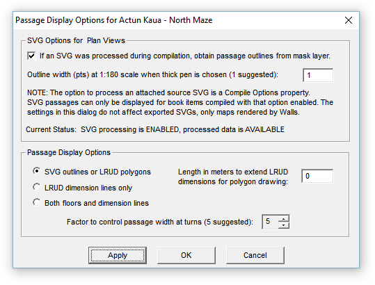
This dialog controls how passage wall information is displayed on maps. It is accessed by clicking the Passage button the Map Page's control panel, or by double-clicking the Passage Outlines tree node on the Segments Page. All but one of these settings will be preserved in the workfiles for the compiled project tree item. The outline width, an SVG-specific setting, applies to all projects.
These options have no effect if passage drawing is not enabled on the Map Page (Passage check box), or if the compiled data set has neither processed SVG data or passage dimension data. The latter can be conventional LRUDs, LRUDs with a specified facing direction (no associated vector), passage wall shots, or a mixture of all kinds.
It may help to know the order in which enabled map objects are drawn on the window or page. First, the window is filled with the background color. Next, the passage representation is drawn. This consists of either filled SVG passage outlines or the LRUD-wall shot representation. Finally, the LRUD dimension lines, grid, survey vectors, station markers, station flag symbols, and station labels and notes are drawn in that order. The result is that passage drawing should never interfere with vectors and annotation assuming you assign non-conflicting colors via the Segments Page.
There's also the option of omitting all annotation, including the survey vectors, to leave only cave passages. To omit vectors, choose the " no lines" line style on the Segments page's control panel when the appropriate (usually main) branch of the segment tree is selected. You can also turn off vectors in a Display map window via the right-click context menu.
SVG Options for Plan Views
The check box specifies whether or not SVG data are to be used for passage rendering when it's available -- that is, when the most recent compilation produced a workfile with extension NTW. Two conditions are necessary for this to happen when a project book item is compiled: 1) an SVG source file with a mask layer is attached to the project tree as a child of the compiled item, and 2) the Compile Options property, Process source SVG if one is attached, is enabled for that item. Note that the status of these two conditions is displayed in this dialog. The information you need to create an SVG file containing a mask layer (named w2d_Mask) is presented in SVG Layer Definitions.
The other SVG-related setting in this dialog, Outline width..., determines the actual thickness of passage outlines when the "thick" line style is selected for the Passage Outlines node of the segment tree. Unlike the other line styles, which produce a minimal-width line regardless of the map's scale, the thick style in this case produces lines that become thicker as the scale becomes larger. The default setting of 1.0 produces a 1-point (1/72 in.) thick line in page units when the scale is 1" = 15 ft. In world units, this is a 2.5-inch thick wall that appears to maintain it's thickness as you zoom in to larger scales. A setting of 2.0 produces 5-inch thick walls, 4.0 produces 10-inch thick walls, and so forth. The outline width setting is not project specific but is preserved as part of the program's profile.
Passage Display Options
The three choices you have for displaying passage dimension data are as follows:
| • | SVG outlines or LRUD polygons - If the SVG mask layer is enabled and available, an outlined passage floor region will be drawn. The outline will either be absent or solid (not dashed) and, if present, will have either a scaled or non-scaled thickness. The line style setting for the Passage Outlines node of the segment tree will determine these characteristics. Choosing the thick line style will cause outline thickness to be scaled as described above. Any other choice besides "no lines" will produce a thin solid outline. The node's setting also determines outline color. If the SVG mask layer is not enabled, passage will be drawn as non-outlined, filled LRUD polygons. In either case, the fill color is that set for Passage floors. Note that while LRUD polygons can be gradient filled, the SVG floor region will be filled with the last-selected solid color. |
| • | LRUD dimension lines - Attributes assigned to the Passage Outlines node of the Segments tree will be used to draw LRUD dimension lines and lines representing wall shots. The thick line style setting, however, will cause thin solid lines to be drawn. |
| • | Both floors and dimension lines - This selection causes both passage floor regions and LRUD dimension lines to be drawn in the styles applicable to each feature when chosen individually. |
Length in meters to extend LRUD dimensions for polygon drawing - A decimal number between 0 and 50 can be entered here to make cave passages more prominent in small-scale area maps. It might also be used to create a metafile map export that can be manipulated in a drawing program to produce gradient-colored passage floors. This setting, which is not stored in the project's database, affects all maps generated during a program session.
The factor to control passage width at turns is a number ranging from 0 to 10. Its purpose is to compensate for the common practice of obtaining just one LRUD measurement set at each station along a cave passage. A value of 0 would instruct the program to simply connect the endpoints of the LRUD cross section bars when constructing passage polygons. In many cases this would cause an undesirable narrowing of the polygon as it either approaches or leaves a station where there is a change in passage direction. A value of 10 causes a second LRUD bar to be generated in such circumstances, one that's rotated (no more than 90 degrees) so that it's perpendicular to the passage that would otherwise be narrowed. This is an approach similar to the one adopted by Larry Fish's COMPASS program. The effect is an enlargement, or smoothing of the passage outline at turns -- not much different from treating LRUDs as if they were the bisector type. The downside is that this can create unrealistic effects when passages are irregular and large compared to shot length. The default value of 5 is a compromise. It rotates the second bar only half as much.
No such passage enlargement occurs when there are multiple LRUDs or wall shot rays obtained at a station. Wall shot rays are defined by way of a recent extension of the SRV data format. For example, here is a sampling of several kinds passage dimension data:
A1 A2 25 270 +3 <13,18,5,0>
A1 - 10 210
- A1 12 300 +10
A1 - 2.5 -- +90
A10 <5,11,2,1,325>
The main distinction of a wall shot is that a minus sign (- or --) is used for one of the names. Like LRUDs, the processed data will be used only for the representation of walls. They don't contribute to survey statistics nor do they appear on the preview map. Reasonably accurate outlines of large rooms and passage junctions can be achieved this way when vector-associated LRUDs would be too limited by themselves.
Note that the last line in the above example illustrates another recent data format addition, an LRUD assigned to an isolated station (A10 in this case). The fifth number is an azimuth, the LRUD's facing direction, which is now optional in any LRUD specification. For more information, see the LRUD and Wall Shots sections under Vector Data Lines.
Ambiguity of Vertical Shot LRUDs
Unfortunately, I've yet to see a set of guidelines that specify what facing direction to assume for an LRUD associated with a vertical shot. That's apparently left up to the surveyors, who are free to pick between two reasonable choices. For the time being, Walls takes the following approach: The direction of the previously established vector takes priority if it is not vertical and the TO name matches the current FROM name. Otherwise, the direction is obtained from the next established vector if it qualifies. If neither vector qualifies, the LRUD is ignored and a non-fatal error is written to the error log. Start-station and end-station LRUDs which are "orphaned" this way are similarly treated. The best solution, of course, is for surveyors to explicitly specify the facing direction, as for station A10 in the above example.
Profiles present yet another ambiguity when shots are vertical. For example, should the station-to-floor distance extend to the bottom of the drop or to the lip of the drop? For what it's worth, the current profile drawing algorithm makes assumptions that favor the lip-of-drop method.