This dialog is invoked by a button on the SVG Export dialog. The choices you make here are not project specific, but will be used for all SVG exports from Walls until the next time they are changed as part of the program's profile. Note that there is a Load Defaults button which resets the controls to values that are currently "hard coded" into Walls. Those particular default settings have worked well for some test cases, but they may not be the ones recommended in future Walls releases. (Which is to say more testing is needed.)
The settings near the bottom of the dialog will be described first since they are the ones you're most likely to change. The controls in the top section, "Adjustment of Merged Features", won't be used routinely, but interested users may want to experiment with them.
Preserve positions of labels and notes
The positions of station labels are determined, at least initially, by offsets specified in the Printer: Map format Options dialog. The settings in that dialog for overlap avoidance, however, are ignored; all labels and notes are normally written to the SVG, leaving you with an opportunity to manually adjust their positions if necessary. Enabling this option causes the individual station-relative positions of both labels and notes to be inherited from a merged SVG if it has content in those layers -- possibly items you've repositioned using Illustrator or another editor. A station label can also be deleted so that it doesn't reappear in a new export that merges the modified SVG. Notes are handled a bit differently. Whether or not a particular note exists in an exported SVG is always determined by Walls settings. (Notes can be omitted for stations with no flags or with only hidden flags -- see Flag and Marker Symbols.) A note won't replace a label as it will on a printed map. When its position isn't inherited, the note is placed above and to the right of the station marker at offsets that depend on type size.
Decimal places in exported SVG file
Most numeric values in the SVG text file, such as page coordinates for vectors, symbols, and artwork, will be written out with this number of places after the decimal point. The units are points (1/72 inches), the same units used in Adobe Illustrator's exported SVG files. (See anote about this.) At normal scales, the quality of rendered artwork rather than geographic accuracy is the main consideration with this setting. File size is another consideration. Adobe's documentation suggests that 3 is the "best choice for most files."
Include LRUD bars when vectors are exported
When this box is checked, LRUD cross-section bars are written to a sublayer named "w2d Lruds" in the SVG file -- see SVG Layer Definitions. The goal is to aid the drafting of wall outlines and cross sections (see below). In Walls2D the bars and vector lines are toggled on and off as a group.
Draw cross section boxes for C-flagged LRUDs
With this option set, a rectangular box will be aligned with and drawn next to the cross-section bar whenever the "C" tag was used in the LRUD specification -- see LRUD Passage Dimensions.
Specified in this section of the dialog are the weighting parameters used by Walls when adjusting artwork to conform to an evolving database of survey data.
Vectors used - When morphing a feature defined by a path object -- for example, a passage wall outline -- Walls examines each individual control point to determine the set of N survey vectors closest to it. The program then computes a new control point position by looking to see how those vectors have changed. The size, N, of the set is 6 by default, but you can specify any number between 1 and 10. Generally, a larger N will produce a smoother morphed result.
In determining how much and in which direction to shift a control point, the vectors in the "closest set" don't all have the same degree of influence. The shift in a control point's position is actually computed as a weighted average of the shifts that would be dictated by the vectors individually. Note that the shift dictated by a vector acting alone preserves the point's perpendicular distance to the vector and also it's proportional distance along the vector's length. The formula used for computing a vector's weight is
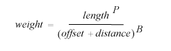
where length is the vector's horizontal length and distance is the horizontal distance between the vector (nearest point along its length) and the control point. The remaining terms in the formula are specified with the next three dialog settings.
Length exponent - Parameter P specifies to what degree a vector's influence (or weight) increases with its horizontal length. If P is zero, a vector's length is irrelevant provided it's no smaller than a specified minimum (see below). The default value for P is currently 0.5.
Distance exponent - Parameter B specifies to what degree a vector's influence drops off with its distance from the control point. This is perhaps the most important parameter to consider. The default setting is 2, but other values, say between 1.5 and 3, might be appropriate. A small value (coupled with a large N) would give a smoother result, but it could also assign too much weight to vectors completely "out of view" of the survey team member who sketched the cave feature. Conversely, a value too large can produce an occasional jump, or discontinuity, in a path that was originally smooth. This happens when the closest vector sets for two adjacent control points are significantly different in the way they have changed -- a "bad" vector present in one but not the other.
Distance offset - When the control point's distance to a vector is zero (or very close to zero) the vector's weight should be very large but certainly not infinite. Also, a large weight due to a near-zero distance can cause path discontinuities near where vectors (possibly more than one) and paths cross each other. A positive value entered here will help prevent this. The default offset is 0.01 (one centimeter).
Minimum Hz length in meters of vectors used - Vectors with horizontal lengths smaller than this value will be ignored in all adjustment calculations; they will not take up membership slots in the set of N vectors closest to a control point. Ideally, whether or not a survey vector is significant should depend on where it's located, say in a big room as opposed to a narrow crawlway. Since the program can't distinguish between such environments, a compromise minimum length has to be chosen. The default value is one meter.
I've found that changes to the weighting parameters often have little noticeable effect on a map's appearance -- particularly when a high quality survey evolves through least-squares adjustments, a process that tends to smooth out local discrepancies between old and new data. Furthermore, the common situations where they might matter the most can be dealt with by other means. One such case is when major survey blunders are being corrected. Another is when passage detail exists far away from any survey shots, as in sketched passages that haven't actually been surveyed. In the first case, a manual touch-up in the region of the blunder is normally all that's needed. In the second case, inserting a few dummy shots (floated vectors) in the data and drawing should smooth things out nicely. The weighting parameters can usually be left at their defaults or at whatever you believe works best for a particular cave.
Adjust features when any station's coordinate changes... - A feature adjustment is considered unnecessary if the maximum difference between a vector's endpoint coordinate in the merged file and the corresponding coordinate in the database is less than this distance in meters. If an adjustment is required, the maximum distance actually found is reported when the operation completes (assuming you haven't chosen to launch Walls2D upon completion). The default maximum distance is 0.3 meters. This feature significantly speeds up a common operation: launching Walls2D with different views of an existing map.
Load Defaults - The choices you make in this dialog, if it's closed with "OK", are remembered the next time you export an SVG. Click this button to temporarily discard those choices and reinitialize the fields with default settings. (The latter may not be optimal and will likely change in future program releases.) If you then decide you don't like the defaults, "Cancel" the dialog to keep your last saved settings.