Clicking the button labeled Scale & Position... on either the Map Page or Page Layout control panel accesses this dialog, which allows you to define precisely scaled and positioned views for printing and export purposes. Changing the dialog's values and selecting OK will immediately update the page layout and map page's preview map.
The View Direction is specified in degrees with respect to either grid north or true north, depending on whether or not you selected the option to generate grid-relative coordinates during compilation -- see Properties: Geographical Reference Page. The text to the right of the entry field will indicate which was the case.
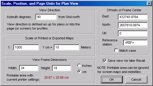
The Scale of Printed or Exported Maps section allows you to specify an exact scale in either of two ways: as a scale ratio or as a unit equivalence. Entering a number into either field will update the other field automatically. The scale, along with the view frame dimensions (see next section), will determine the view width in survey units. This width, in turn, defines the region shown in screen displays and in the Map Page's preview map. Note that page units, inches or centimeters, can be specified with a unit toggle in the next section of this dialog. The survey units, feet or meters, will have been determined prior to invoking the Review dialogs -- see Properties: General Page.
The View Frame Dimensions section is where you specify the frame size in inch or centimeter page units. This frame is a rectangle, the outline of which you may or may not choose to draw on the printed map -- see Map Format Options. The dimensions you input here, along with the scale, will determine the map coverage -- that is, the view width and height in survey units. Unlike versions of Walls prior to B5, the frame dimensions are a property of the compiled project branch and will be saved in the database. Furthermore, plans and profiles can have different frame dimension settings. These settings will persist until changed in this dialog or until workfiles are purged. Also, unlike prior versions of Walls, the frame dimensions specified in the Map Format Options dialog determine only the initial frame size for new compilations.
Note: A drawn frame outline will surround the view but not cover any part of the view. Therefore, when taping together pages of multi-page maps, thick frame outlines can be trimmed off entirely to facilitate accurate matching of plot segments.
Displayed in red, for your information, are the dimensions of the page's printable area, which are dependent on the currently selected printer and page settings. The printable area will be smaller than the page itself depending on the specific printer model. An 8.5" x 11" sheet, for example, might provide a printable area of 8.27" x 10.23". If the specified frame dimensions (plus frame outline thicknesses) are larger than this, printed maps will be truncated. You'll be warned of such truncation during subsequent print or print preview operations. You will not be warned, however, if there is no room outside the frame to print the legend text (in case you've chosen such a legend position). In the Page Layout dialog, where the view frame and printable area are shown graphically, you can experiment with different printer settings.
If your objective is to produce metafiles for import into drawing programs, the size of the printable area can be ignored. The frame dimensions alone will determine document size. Starting with Walls B5, metafiles and printed maps don't have separately specified frame dimensions. Changing the frame size defaults in the Map Format Options dialog, metafile or printer version, will change them for both output types. Currently, the maximum allowed width or height for a Walls plot is 72 inches. To go beyond that you will need to output separate plots (or files).
The Offsets of Frame Center section allows you to position the center of the frame so that it corresponds to a specific set of coordinates, or rather a set of coordinate offsets with respect to a specific named station. (To center on a named station, set the offsets to zero.) Each time the dialog is opened, the station is automatically set to the reference station for the current network component. By changing either the reference station or the offsets you can reposition the view without rescaling it. If you enter a station name and try exiting the dialog, an error message is displayed if the name isn't found in the database. A checkbox option allows you to specify a case-sensitive name search.
Important: To be safe, you should inspect this dialog immediately prior to printing. Operations on the preview map (zooming and panning) can change these settings, if sometimes only slightly. For this reason, it's common practice to leave the Save view for later Recall option turned on when you close the dialog. (See Save and Recall.) This option is a user preference that's preserved between program sessions.