![]() This dialog is accessed from the File menu, the Adjusted Totals dialog, or more simply via the tool bar icon that resembles a printed page (shown here). The reporting feature is enabled whenever a compiled project branch is being reviewed. Only data that are summarized in the Adjusted Totals dialog will be included in the report -- and that's controlled by settings on the Segments page. Portions of the survey component being reviewed can be excluded by expanding or detaching branches of the segment tree.
This dialog is accessed from the File menu, the Adjusted Totals dialog, or more simply via the tool bar icon that resembles a printed page (shown here). The reporting feature is enabled whenever a compiled project branch is being reviewed. Only data that are summarized in the Adjusted Totals dialog will be included in the report -- and that's controlled by settings on the Segments page. Portions of the survey component being reviewed can be excluded by expanding or detaching branches of the segment tree.
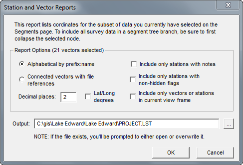
There are currently two basic report formats: 1) an alphabetical listing of stations with their coordinates and assigned notes and 2) a list of stations and their coordinates organized as vector sequences (a possibly useful export format). Two additional format options are available with the alphabetical station listings. First, you can choose to have only noted stations included. This should shorten the list considerably. Second, by selecting Include only flagged stations, you can group the listed stations by the names of assigned flags (e.g., entrances, leads, etc.). If a station has several flag assignments, it will appear in the report several times. The flag sections will be ordered alphabetically by flag name. If you select this option, unflagged stations will not be listed at all.
For both station listings and vector listings you can choose to Include only vectors or stations in current view frame. That's the view frame specified in the Scale and Position dialog that defines a printed page. (Its height can be different than what's shown on the Map page's preview map.) In the case of the vector list, a vector's FROM and TO stations will both appear as adjacent lines of the report if at least one of the two stations is inside the frame. When a station is out of the frame, its corresponding line in the report will have an appended ">" character.
Use the Decimal places edit box to specify the number of digits after the decimal to show for UTM coordinates. If Lat/Long degrees is the requested coordinate type, 4 will be added to this number.
At the bottom of either type of frame restricted report, the minimum and maximum coordinate values of stations actually located inside the frame are listed. In vector reports, the number of vectors crossing the frame boundary (i.e., the number of appended ">" characters) is also listed.
When the dialog is opened, the Output edit box will be initialized with a name (extension LST) constructed from the reviewed item's base name, the path being the project's work folder. Of course you can change this, but you'll need to remember the file's name and location if you want to easily access the file during a future session. A soon as a report is generated it's automatically opened in a Walls edit window. The file is an ordinary tab-delimited text file.
Jumping from Listing to Data File
In vector listings the rightmost column is a colon-separated filename and line number (e.g., SURVEY02:1023) that locates the vector in the original data. An easily overlooked feature is the ability, when editing the report file in Walls, to double-click this location field to open an edit window into the survey data file with the line highlighted. (For example, you may want to use this feature to find vectors that have been assigned an obscure, possibly mistyped, segment name.) This feature, however, is enabled only when the file extension is LST.
Apart from the location field, the vector and station lists have similar formats. The location field in a vector list has an appended minus sign to mark a TO station for which the immediately preceding station is the FROM station. Lack of a minus sign indicates the start of a traverse. As noted above, the character ">" might follow the location field and possible minus sign to mark an endpoint station that's outside the view frame.
Requirements for Generating UTM or Lat/Long Coordinates
The coordinates displayed in reports, and stored in exported data will be georeferenced if these two conditions are met:
| • | On the Geographical Reference page, the checkbox option Coordinates: UTM/UPS grid-relative must have been enabled at the time of compilation. You can't enable this option without also specifying a geographical reference. This reference, which can be inherited from a higher-level project tree item, determines the geodetic datum and coordinate system of displayed and exported data. |
| • | The #FIXed points in your SRV data files, of which there must be at least one, are entered as UTM eastings and northings (or Lat/Long). Also, each SRV file with fixed points must have in its property settings a geographical reference with the appropriate zone and geodetic datum specified.. |