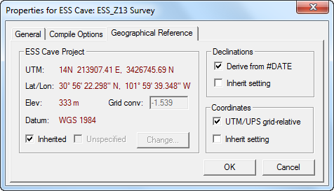
The Geographical Reference page displays (in red-colored type) the geographical reference position you've selected for this item in the project tree. Selecting a reference position activates the controls on the right of this dialog, which allows you to generate UTM coordinates and/or use #Date directives for the automatic calculation of magnetic declinations. In this example we are viewing the settings for "ESS_Z13 Survey", which show that the reference position is being Inherited from a parent node, "ESS Cave".
Unchecking the Inherited box enables the Change button along with the Unspecified check box, which, if checked, makes it clear that no geographical reference is being used. When you first create a project, the root folder's geographical reference is unspecified and the related settings for all child items are inherited. You could very well leave it this way if you have no need for UTM coordinates and date-derived declinations. Changing anything but the Coordinates setting (which affects output for this item alone unless the setting itself is inherited) will invalidate the workfiles of ancestor and descendent items in the project tree, causing blue tree icons to become red icons. The Declinations and Coordinates check boxes are described in more detail below.
When it's enabled (not grayed) the Change button brings up a version of the Geographical Calculator. Although the calculator can be used for other purposes, the only calculated results that are needed for survey data processing are the grid convergence and the magnetic declination. Both depend on the selected geographical position. The declination also changes with time, and therefore your survey vectors must have been assigned dates if the program is to automatically calculate declinations.
Declinations - Derive from #Date
When this option is selected, default declinations (otherwise zero) will be automatically supplied by the program when data files containing #DATE directives are compiled. A #Date directive then becomes equivalent to a #Units directive with the single argument DECL=x, where x is the declination derived from a model of the Earth's magnetic field. The use of this option, however, will not deactivate all DECL specifications that might actually appear on #Units directive lines. The two methods of specifying declination will simply override each other depending on the ordering of directives in your files.
The mathematical model used to estimate the Earth's magnetic field is known as the International Geomagnetic Reference Field (IGRF), which currently supports dates in the range Jan 1, 1900 to Dec 31, 2014. It is the same model used by GEOMAG, a program maintained by the NOAA's National Geophysical Data Center (NGDC). An online version of GEOMAG along with more information on the model is available) at the NGDC website.
Besides providing a declination angle, both GEOMAG and the Walls calculator estimate the intensity of the magnetic field's horizontal component. Magnetic compass readings are considered by some to be unreliable if this intensity is less than about 5000 nT (nanotesslas), which is often the case for locations above 70° N latitude.
The IGRF model's declinations are usually accurate to within a degree, depending on your location. Perhaps more important than absolute accuracy, however, is the ability of the model to predict the change in declination, which is very significant over a period of years. This can be of great help as we try to calibrate new compass readings against those taken in years past, when only dates, not declinations, were recorded in field books. For future work, various schemes of calibration are possible, such as having each surveying team routinely take readings on a few physical features at known (or agreed-upon) true north orientations at the cave entrance. Any consistent deviation from the IGRF predicted value, which in reality is a combination of both model error and instrument error, can then be expressed as a compass (IncA=) correction. In fact, differences between instruments not properly calibrated against each other are likely to be a more serious problem than uncertainty about declination.
A mixture of model-predicted declinations and declinations taken from other sources (entered explicitly as DECL=n), even when the latter are believed to be more accurate, is probably a bad idea. I recommend using just the model, or consistently employing some other method of keeping measurements comparable over time and between surveying teams. Remember that during a Walls data compilation, a compass and tape vector's true north-relative direction is obtained as follows:
<compass reading> + <IncA correction> + <computed or specified declination>
When the option to generate UTM/UPS coordinates is in effect (see below), the grid convergence is then subtracted from this value to obtain the grid-relative direction.
You'll notice that the geographical calculator in Walls shows declinations precise to two decimal places, even though we can't depend on them being much closer than about a degree of the true value in some regions. The displayed precision at least gives us some sense of the declination's dependence on time and position. Given the model's limited accuracy, it's probably sufficient to choose a reference position somewhere within the cave area (no farther than 40 km away) and stick with it throughout the course of the project.
Coordinates - UTM/UPS Grid-relative
When the "UTM/UPS Grid-relative" box is checked, the coordinate listings and maps generated after compilation will be grid-relative rather than true north-relative. The coordinates produced will be either Universal Transverse Mercator (UTM) or Universal Polar Stereographic (UPS), the latter being an option in polar regions. The grid convergence angle used for the conversion from true north to grid north will be the one shown in this dialog, labeled Grid Conv. The value will be subtracted from true north-relative azimuths to obtain grid-relative azimuths. Normally, this angle is the actual UTM/UPS grid convergence angle associated with the reference position (as computed by the calculator); however, advanced users can change the Grid Conv edit box contents, thereby producing any desired amount of rotation. If this is done, the generated coordinates will not be strictly UTM or UPS, even though the coordinates on a listing might appear to be. This value also establishes the default GRID correction that will be applied to #FIX coordinates when true north-relative coordinates are wanted. (To enable the Grid Conv edit box you still need to specify a geographical reference position.)
In the example above, since "UTM/UPS grid-relative" is checked, a negative grid convergence (-1.539 degrees) will be applied so that all generated maps and coordinate listings will be based on UTM grid north instead of true north. This assumes that the convergence angle was derived from the reference and not edited.
The coordinate type produced in a compilation, UPS or UTM for a specific zone, is determined by the geographical reference assignment of the project branch selected for compilation. Usually, a child item will inherit its geographical reference from its parent; however, a descendent item might very well have its own reference assignment and consequently a different basis for defining #FIXed positions. A Walls project might therefore overlap a zone boundary (or, less likely, the equator or one of the UPS/UTM boundaries at 84° N and 80° S). The final result of a compilation, in any case, will be a consistent database with coordinates all either UPS or UTM in a single zone.
In polar regions, the choice of UPS over UTM can result in more accurate coordinates due to less scale distortion. Although a compass-and-tape survey with one fixed point would not have better loop system statistics, the coordinates of distant stations would more likely fit those of satellite estimates. The Geographic Calculator topic describes how to specify UPS for a survey's geographical reference.
Automatic Zone and Datum Conversion
When appropriate, Walls will automatically convert coordinates in one UTM zone and geodetic datum, say zone 14, NAD27, to coordinates in a different zone and datum, such as zone 13, NAD83. Thus UTM coordinates that are technically out-of-zone are possible in a compiled database. This can happen when a child node of the project tree is assigned a different geographical reference from that of the parent node being compiled. This feature allows you to easily construct projects with data overlapping a zone boundary, or projects with fixed points defined in different datums. (The Geographical Calculator topic describes how to express coordinates in either of two adjacent UTM zones.).