This dialog is accessible from two locations: A button on the Map page control panel labeled Grid, and a segment tree icon labeled Grid on the Segments page. (Double-clicking the icon opens the dialog.)
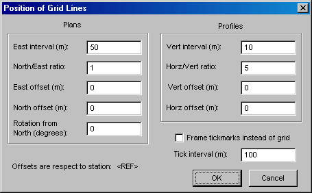
Here is where you to specify grid properties such as origin, spacing, and orientation. (As with most other map features, the color and line style of the grid are settings on the Segments page.) By default, the grid origin is located at the component's reference station, but you can specify East and North offsets for plans and vertical and horizontal offsets for profiles.
Grid intervals for plans are specified as an East interval in survey units and a North/East ratio. For initial compilations, the default East interval is 100 survey units and the North/East ratio is 1.0, which produces a square grid. In the above example, the "m" suffixes indicate that the current review units are meters (as specified on the General page of the Properties dialog). Similarly, profile grid intervals are specified as a vertical interval and a horizontal/vertical ratio. Here, the ratio 5 produces grid cells five times as wide as they are tall -- 50 meters wide in this case. Thus the grid dimensions of profiles are independent of the view direction.
Plan grids can also be rotated clockwise by an amount specified in degrees. Finally, the dialog features a Frame tick marks instead of grid check box and an associated Tick interval field. This gives you the option of replacing the grid with tick marks along the frame's border. The length and thickness of those tick marks are setting is the Map Format Options dialog.