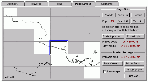
You should examine this page of the Review dialog before sending output to the printer. It shows a simplified image of the printed map in the context of a grid, each cell of which represents a view frame of the currently assigned dimensions. (See Scale and Position Dialog.) The selected cell is indicated by a blue rectangle representing the printable area of the page as determined by your current printer settings. Since anything outside this rectangle can't be printed, you must insure that the view frame lies entirely within it to avoid producing a truncated map. (Upon printing you'll be warned of this situation.)
Survey lines representing data in the selected component of the compiled item are shown in black. (Fixed stations appear as small squares.) Unlike the preview map, however, surveys that reside in detached branches of the segment tree are not shown since they will not appear on the printed map.
To obtain a multi-page plot, you can right-click with the mouse on the desired frames, turning them white instead of gray -- or you can Select All non-empty frames automatically with one button click. The sheets of a multi-page printout, when taped together, will perfectly cover a region as long as the paper on and outside the frame outlines is first trimmed away. (Thick frame borders will not obscure plotted surveys.)
The above highlighted cell arrangement will produce a multi-page plot. The pages will be printed in row-column order, and the selected (blue-outlined) cell establishes the zero reference for frame labeling. In this example, the top-left, partially visible frame is labeled -3:-4 (row -3, col -4) and the bottom-right highlighted frame is labeled 1:2. To maintain consistent frame labeling for a large project area, you'll probably want to select (but not necessarily highlight for printing) the cell in the top-left corner of the entire project region. The region's frames, whether printed or not, can then be designated 0:0, 0:1, 0:2, ..., 1:0, 1:1, 1:2, ..., etc.
How do you change the selected cell without highlighting it for printing? Double-click the cell you want to select. (This also highlights and centers the cell in the grid display.) Then right-click the cell to toggle off the highlight (color it gray). In order to accomplish this you may need to Zoom In/Out or pan the display by CTRL-dragging with the mouse.
The selected, blue-outlined cell also indicates the view frame currently displayed in the Map page's preview map. It's the frame from which screen maps are generated via the Map page's or Segments page's Display button. It's also the frame used for metafile output. Therefore, double-clicking a cell in this dialog is an easy way to accurately reposition the preview map for single-frame output.
Page Layout Controls
| • | Zoom In/Out - Use these buttons to change the scale of the grid. Initially, the only selected cell will be that of the preview map's view frame and it will occupy more than a third of the grid window's width. Another method of navigating the grid is CTRL-dragging with the mouse, which pans the grid as it would the preview map. Also, double-clicking the grid will select, center, and highlight a specific cell, thereby repositioning the preview map. |
| • | Default - This centers the selected cell at the original magnification while unhighlighting all other cells. |
| • | Select All - Highlights (makes white) all cells and only those cells that cover any part of the current survey component. For reasonable frame sizes, white cells will cover the entire component except for segments hidden via segment attribute settings. One caveat: Walls will highlight no more than 500 cells and will notify you if this coverage is incomplete. |
| • | Clear All - Unhighlights all cells, including the selected (blue outlined) one. A subsequent attempt to print or print preview will produce an error message. |
| • | Scale & Position - Opens the Scale and Position dialog as does the like-labeled button on the Map page. There you can adjust frame size (grid spacing), map scale, and specify the preferred page units: inches or centimeters. When the dialog is dismissed, the Page Layout page is updated to reflect any changes. This will remove highlighting for all but one recentered (and selected) frame. |
| • | Format opts - Opens the printer version of the Map Format Options dialog. Like the "Format..." button on the Map page, this lets you review and change global format settings which aren't project-dependent: Default marker and flag attributes, line thicknesses, text fonts, etc. |
| • | Page Offsets - Opens the Page Offsets and Legend dialog, which lets you position the frame on the page, set an out-of-frame plotting distance, and to position the legend text (or omit it). |
| • | Landscape - Checking or unchecking this box will toggle page orientation between landscape and portrait modes. It changes not only the display (outlined printable area) but also the setting for the currently assigned Windows printer. As a convenience, Walls automatically switches the printer to landscape mode when it starts up. |
| • | Printer Setup, Print Preview, and Print Map - These buttons invoke the same basic print operations as those on the File menu. You'll normally want to use them in that order. Changes within the printer setup dialog will be reflected in the page layout display as soon as the dialog is dismissed. Print Preview lets you see an image of what will be printed given your particular format and segment settings. It's especially useful when a multi-page plot is being generated. (Might save you a lot of paper.) |