On the Segment page of the review dialog there are six colored buttons for assigning colors to map features. Clicking any one of these buttons displays a drop-down window containing a palette of 40 solid colors along with some feature-specific coloring options. For example, the drop-down window for assigning vector colors might appear as follows:
|
One of the choices will have a sunken appearance to indicate the selection currently in effect. In this example, "Color by depth" is currently selected and will remain so if this dialog is cancelled. (Clicking anywhere outside the dialog will cancel it.) Although the image at left doesn't show the mouse cursor, the raised appearance of the "Color by stats" button is due to the cursor being positioned above it. Clicking that button will open a dialog for editing a color range, or gradient. If the colored rectangle to the right of it is clicked instead, the gradient already defined for statistics coloring is directly selected and the dialog closes.
|
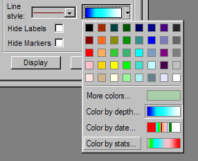
All three of the "Color by" options beneath the 40-color palette behave similarly. Clicking the right side chooses the gradient currently defined for that type of coloring. Clicking the left side opens the Color Gradient Dialog which allows you to edit the gradient prior to selecting it. The "More colors" button also behaves this way, but instead of opening the gradient dialog, it opens the standard color picking dialog that's common to many Windows applications. You can use it to select a solid color that may not be present in the palette. The rectangle to the right of "More colors" displays the solid color last chosen for this map feature -- pale green in this example. This is the color used for some types of program output where gradient coloring isn't applicable. Note that within the standard color dialog you can add your favorite solid colors to a "Custom colors" palette that will be preserved across separate invocations of the program.
Notes on Gradient Coloring
Currently, gradient coloring can be selected only for vector lines (in the main portion of the segment tree) and for LRUD-based passage floors. All other color dialogs contain just the palette and "More colors" options. Furthermore, the following should be noted regarding the assignment of gradients:
| • | Gradient coloring is applicable only to printed and internally displayed maps and also to exported metafiles. The last chosen solid color, not the selected gradient, will be used for shapefile, VRML, and SVG exports. Also, the last solid color chosen for Passage floors will be used for floor coloring when the passage outlines are based on a source SVG instead of LRUD measurements. |
| • | When the map is drawn, each survey vector or LRUD polygon is rendered with a single solid color, not a range of colors. For example, when vectors are colored by depth, the elevation of the vector's midpoint is used to select a color from the color-by-depth gradient. |
| • | Like any vector line style assignment, a gradient assigned to the main branch of the segment tree will be overridden by colors (solid or not) assigned to child branches. It may be necessary to temporarily set child branches to inherit coloring from their parents when examining the effects of gradient coloring. |
| • | The database for a compiled project tree item stores just one gradient for each of the three different types -- one for color-by-depth, one for color-by-date, and one for color-by-stats (component F-ratio). For example, if you redefine the color-by-date gradient, it affects all parts of the map where date coloring is assigned. |
| • | The gradient definitions are stored in workfiles with extension .NTAC, three gradients per file, which are preserved across compilations (but not purges). The NTAC files are considered part of the NTA file set that's optionally stored in a backup archive. |
An advantage of using one of the gradient types for coloring LRUD passage floors (backgrounds) is that differently colored passages will properly appear above or behind one another. Upper levels will overlap lower levels on plans and foreground passages will overlap background passages on profiles. Vector lines are normally drawn after all the passage floors are drawn. This means that unless a vector overlaps a floor polygon drawn earlier with the same color it will ordinarily not be obscured by the passage representation. When your main goal is to show passage, there are several ways you can prevent the display of unwanted vector lines. In approximate order of usefulness they are:
| • | Use the Segment page's control panel to give selected segments the thin solid line style and the same color gradient as the passage floors. Such vectors will be sorted "back-to-front" along with the floor polygons and rendered at the same time. Only if vectors have no corresponding LRUD measurements will they appear as lines instead of polygons. In either case they will be obscured by higher-level (or foreground) passages. |
| • | Give vectors the same gradient as the floors but instead of the thin solid line choose either a dashed line or the thick line style. (If the latter, set the thick line width to one pixel in Map Format Options.) In a plan view this causes vectors with floor polygons to be visible as lines only when they pass beneath an upper-level passage that's colored differently. Selecting such vectors with the mouse is easier when they can be seen -- perhaps the only advantage of this approach. |
| • | Give vectors the "No line" style but again set their gradient to be the same as the floor gradient. This will produce the same effect as the first method. The difference is that when passage display is turned off the vectors won't be represented at all. |
| • | A quicker but less selective way to accomplish this for screen maps is to toggle off "Show Vectors" on the map window's context menu. With "Show Passage" enabled, this turns off any vectors with a different color assignment. With "Show Passage" disabled, this turns off all vectors. |
Whether drawn as lines or represented only by floor polygons, vectors can still be highlighted as described under Vector Properties Window.
See Color Gradient Dialog for more information on gradients and how they are defined.