Difference between revisions of "Qucs"
imported>Pew |
imported>Pew |
||
| Line 79: | Line 79: | ||
* [http://qucs.sourceforge.net/docs/workbook.pdf Qucs Workbook] | * [http://qucs.sourceforge.net/docs/workbook.pdf Qucs Workbook] | ||
| − | |||
| − | |||
| − | |||
| − | |||
[[Category:Needs restoration]] | [[Category:Needs restoration]] | ||
Revision as of 07:27, 3 January 2018
TODO: Migrate to software page
Qucs, the Quite Universal Circuit Simulator, is a Free Software integrated schematic capture and simulation tool for digital and analog signals. It supports DC, transient, AC and digital simulations as well as parameter sweeping. It does not currently support Monte Carlo simulations, although with some crude Bash and QtOctave work, this can be overcome. If you don't mind using extra tools for Monte Carlo simulation and are willing to fudge the exact model of op-amps used in Lab-in-a-Box projects, Qucs and be used to complete assignments in ECE 2074 Electric Circuit Analysis Laboratory.
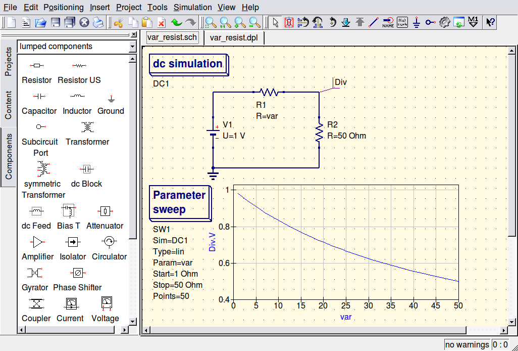
Screen Shot
Monte Carlo Simulation
The following steps show how to produce voltage and current histograms in a simple sources-and-resistors circuit.
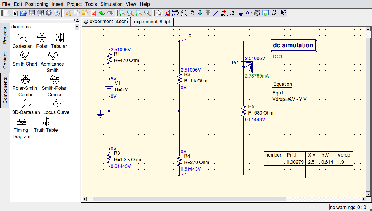
The first step is to draw your circuit and make sure it simulates as expected. Use a dc simulation, a current probe to measure the current you're interested in and two labels and a difference equation to define the specific voltage drop you're interested in measuring. An example is presented below.
It is necessary to define a resistor with a variable value within a given tolerance. This can be accomplished with the following circuit. You can recreate this circuit yourself or download res_tol.sch from http://vtluug.org/files/qucs.
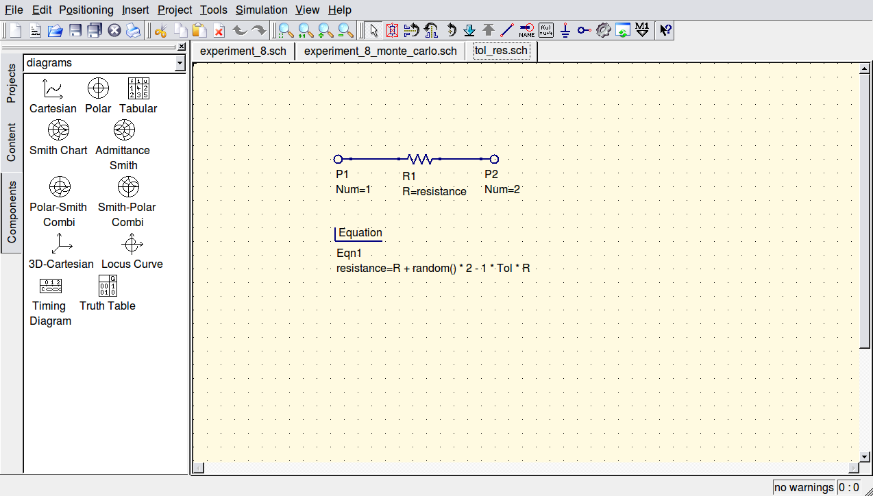
Next, replace all the regular resistors in your original circuit with subcircuits of the previously made varying resistor. For randomized results on each run, it is necessary to provide a seed to the random number generator. For now, define an equation the likes of z=srandom(1337). The actual value is just a placeholder and will be replaced when the simulations are run from the commandline.
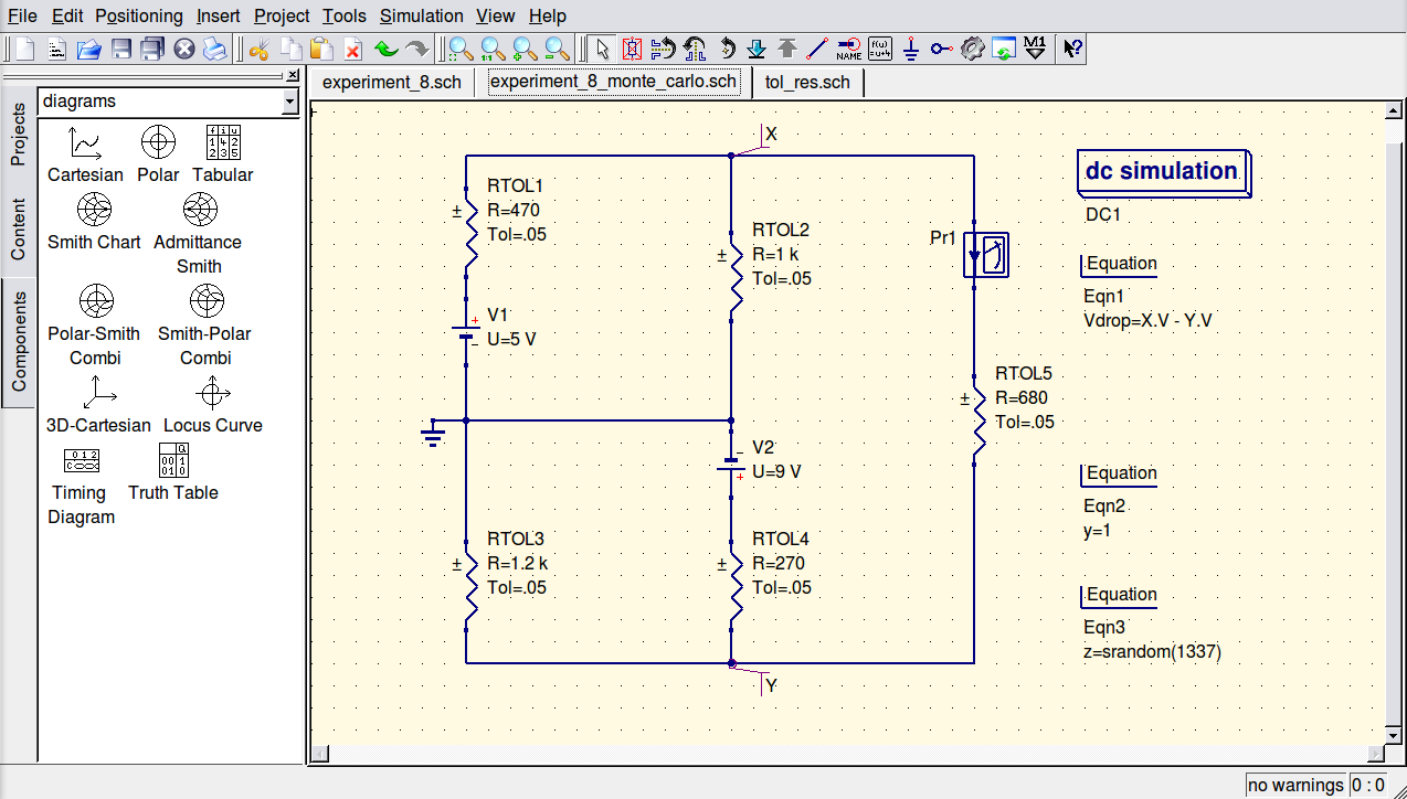
Save and run the circuit. You should be able verify that the result changes slightly given different random number seeds. You'll now need to automate running the simulation with different seeds. Open up the netlist by selecting Simulation->Show Last Netlist. Copy the contents of this file into a text editor and save it as monte_carlo_netlist.txt. Then, paste the following bash script into a text editor and save it as monte_carlo.sh. The variables of the script can be edited to suit. The value of REPLACEME should be the unique placeholder value used as the pseudo-random number generator seed earlier. The value of NUM determines how many times the simulation is run.
#!/bin/bash

INFILE="monte_carlo_netlist.txt"
REPLACE="1337"
OUTFILE="monte_carlo"
NUM=400

echo -n > "${OUTFILE}.temp"
for i in $(seq 1 $NUM) ; do
	sed s/$REPLACE/$(date +%N)/ $INFILE | qucsator | sed -nr \
		-e '/<indep Vdrop/,/<\/indep/p' \
		-e '/<indep Pr1.I/,/<\/indep/p' \
		| sed -nr '/-?[0-9]\.[0-9]+e[-+][0-9]+/ p' \
		>> "${OUTFILE}.temp"
done


echo -n > "${OUTFILE}.dat"
echo -n "values=[" > "${OUTFILE}.m"
odd=1
for r in $(cat "${OUTFILE}.temp") ; do
	if [ $odd -eq 1 ] ; then
		echo -n "${r} " >> "${OUTFILE}.dat"
		echo -n "${r} " >> "${OUTFILE}.m"
		odd=0
	else
		echo $r >> "${OUTFILE}.dat"
		echo $r >> "${OUTFILE}.m"
		odd=1
	fi
done
sed -i '$ s/$/]/' "${OUTFILE}.m"
Make the script executable and run it:
chmod +x monte_carlo.sh
./monte_carlo
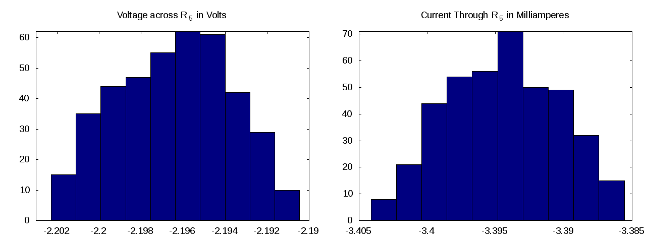
If all goes well, it should generate a monte_carlo.m file. Open this up with QtOctave and plot a histogram. The Plot->2D...->Histogram menu selection is a good start, although it seems a little buggy and you many want to start with the command it gives you and tweak the Octave plot command until you have proper labels and so on.
If you want to stitch the voltage and current plots together into one image, you can use ImageMagick for that:
convert voltage.png current.png +append voltsamps.png
Here is an example final product.
